
Posted on December 27, 2019
Restoring an Altair 8800b Turnkey computer part 1 – Power supply and capacitors
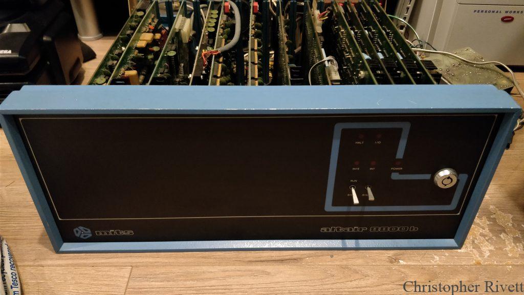
In March of 2018, I was fortunate enough to receive an Altair 8800b Turnkey computer. The history of this particular machine is unknown other than it was shipped over here to the UK from the US years ago and no one knows when it was last used. The machine came just on its own without the key to turn it on or any kind of floppy drive to boot from. This presented me with a few challenges before I could get the machine fired up.
I had read that I could probably restore the original power supply to working order using a variac power supply to gradually bring it up to mains voltage while checking for shorts. I decided that rather than mess with a 41 year old linear power supply that had a massive (and rusty) transformer in it, I would seek to replace it with a modern supply of some kind. If I was based in the states, I probably would have taken the variac route since the power supply is only rated for 120V mains voltage whereas we use 230V here in the UK. Using modern switching power supplies allowed me to leave the machine looking original from the outside and allowed it to function as originally intended on 120V mains while also now supporting 230V mains voltage. With a cheap US to UK travel passthrough plug I could leave the original flex and American plug intact rather than irreversibly chopping it off and wiring up a British plug instead.
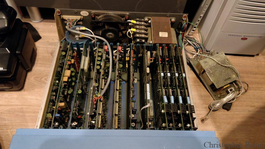
Since the Altair 8800 line of computers don’t regulate voltages from the power supplies themselves, each S100 bus card has its own voltage regulator, sometimes multiple to deal with this. This isn’t a very efficient way of doing things so a possible modification would be to remove all regulators from the cards and use a regulated power supply in place of the original. This creates a couple of drawbacks however. First being that using modified S100 bus cards in an unmodified machine would fry them with full unregulated voltages running directly into them. Secondly unmodified S100 cards will likely not work correctly either as they will try regulate down voltages that are already the target voltage at the input to the regulator. This was not something I wanted to do. Instead what I did was get 3 separate power supplies (two 16V supplies, one set for -16V and the other for +16V and a 7.5V supply) to supply each of the voltage lines. I could get away with a 7.5V supply for the 8V line as the regulators can still regulate this down to 5V and as an added bonus, the slightly lower input voltage will keep the regulators running cooler than they would otherwise. After removing the original supply and packing it up for safe keeping (incase anyone ever wanted to properly restore it in the future), with some help from my Grandpa we made a plastic plate to hold the new supplies in place. This is pictured below, fitted in place with the supplies. We also added some connectors so the live and neutral wires could be disconnected easily.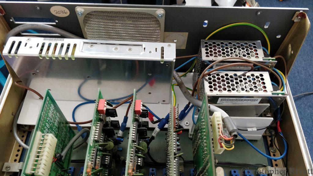
You will notice that the fan has also been removed, it was an AC 120V fan so I had no easy option to reuse it even if I wanted to. The new power supplies are designed not to need any additional cooling and as far as I know, the fan was mostly for the power supply anyway. I will keep an eye on the temperatures and add a fan at a later date if required, but for now I have decided to leave it as is.
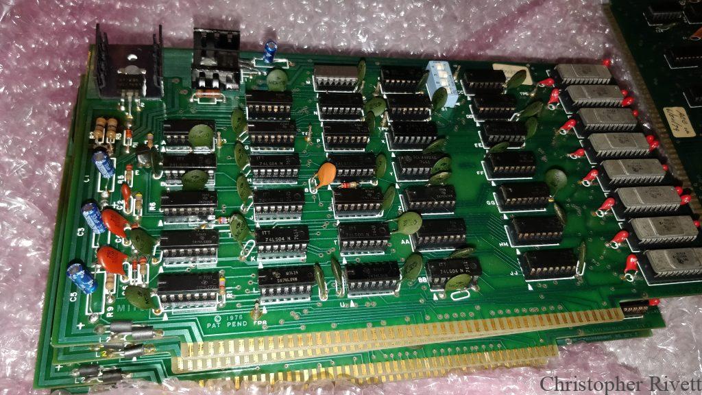
The capacitors on the S100 bus cards had started to go bad so I had to deal with these before attempting to power on the machine as well. The originals were axial (one leg on each side) capacitors, but finding suitable axial replacements proved to be extremely expensive compared to the radial (both legs on one side) equivalents. Thankfully modern capacitors are a bit smaller than their 1970s counterparts in this case. This meant even though radial capacitors stand vertically rather than horizontally, the ones I ended up using would fit without issue. Some people might be a bit upset that I went the route of using capacitors that look nothing like the originals, and I agree that would have been the better option, but as long as it works I don’t mind. Since the machine looks stock from the outside and still functions as intended I am happy enough.
Below is an example of a couple of the 4K MITS DRAM cards before and after. I don’t think the capacitors I took off were originals but they were definitely ancient regardless! As you can see in the second photo the new modern replacements are much smaller even though they are of an equivalent specification.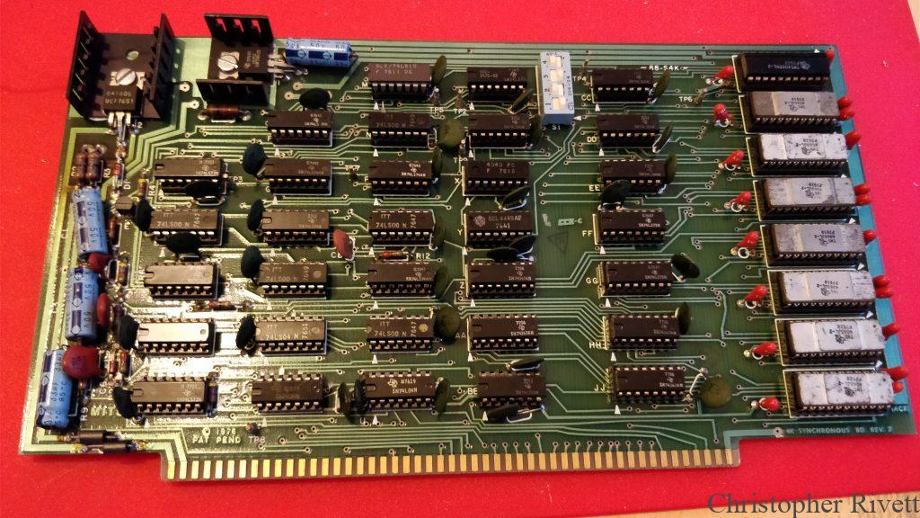
Keep an eye out for more posts soon on other issues I had to solve to get the machine into a fully functional state as well as what software I have had running so far!
Did you have to connect the 2 16v switching supplies together to get +16 and -16 ?
Did the sequencing of the 3 supplies cause any issues? I saw a youtube video where someone said they needed to use a relay to have the power from all 3 applied simultaneously…
The 16v supplies didn’t need to be connected together, each had a + and – output but one had to be grounded to enable the other I believe. Which is why I needed two, as originally I thought I might get away with just the one. I didn’t run into any issues with the sequencing of the 3 supplies, the machine is still working and has run for almost a whole day without issue in the past.
I’ve seen original documentation for the 8800b that show a +18 and -18 volt supply, just curious why you chose a 16v supply instead?
Thanks.
I think either this particular variant used + and – 16v instead, or as the cards usually regulate the voltages down anyway that it didn’t matter. I also seem to remember at the time it was easier/cheaper for me to source the 16v ones.
It would be helpful to document how you can either replace the rotary on/off switch on the front panel or just work around it. It’s basically two switches that I guess are turned on separately when the external rotary key is turned clockwise?